24Hours Tel
0086-139 8951 3573
Free Inqiry
E-mail:[email protected]
24Hours Tel
0086-139 8951 3573
Free Inqiry
E-mail:[email protected]
Inverted flare fittings are one of the most widely used tube connection systems in automotive, hydraulic, and fluid transfer applications, yet they remain poorly understood outside of professional mechanical and plumbing circles. Whether you are tracing a brake line leak on a truck, specifying hydraulic inverted flare fittings for industrial equipment, or simply trying to understand why your compression fitting is not sealing correctly, the principles behind the inverted flare connection system are worth understanding thoroughly. This article covers every practical aspect of inverted flare fittings: what they are, what they look like, how they compare to flare nut fittings, how to install them correctly, and what they are used for across the full range of industries and applications where they appear.
The term "inverted flare" describes a specific tube end preparation and fitting geometry in which the end of a tube or pipe is flared outward and then folded back toward the tube body, creating a double-thickness flare that faces inward into the fitting body rather than outward away from it. This inward orientation is the defining characteristic that distinguishes an inverted flare from a standard (SAE 45-degree) flare, and it is the source of both the connection type's name and its distinctive mechanical behavior.
To understand what "inverted" means in this context, it helps to first understand what a standard flare looks like. In a standard flare connection, the tube end is expanded outward at a 45-degree angle, and the mating fitting nut compresses this flared end against the cone seat of the fitting body from the outside. The flared material faces outward, away from the fitting body, and the sealing load is applied to the outer face of the flare.
In an inverted flare, the tube end is first flared outward in the conventional direction, but is then folded back on itself so that the flared section curves inward, toward the tube body axis. This creates a double-walled, rounded, outward-facing bead at the tube end that seats inside the fitting body rather than against the outside of a seat cone. The fitting nut, when tightened, draws the inverted flare bead firmly into the conical seat inside the fitting body, creating a metal-to-metal seal at the internal mating surfaces.
The inverted flare geometry was developed specifically to address the limitations of single-thickness flares in high-pressure and vibration-intensive applications. Because the flared tube end is doubled back on itself, the wall thickness at the sealing surface is effectively doubled compared to a single flare. This doubled material provides significantly higher resistance to fatigue cracking at the flare root, which is the most common failure point in single-flare tube connections subjected to vibration, pressure cycling, and thermal expansion and contraction.
The inverted flare is standardized under SAE J512, which specifies the 42-degree included angle of the seat cone used in inverted flare fitting bodies. This 42-degree cone angle is one of the key dimensional parameters that distinguishes inverted flare fittings from other flare types and must be matched correctly when selecting inverted flare connectors or inverted flare adapters for a specific application. Using a fitting body with the wrong cone angle against an inverted flare tube end results in line contact rather than surface contact at the seal, producing a connection that leaks or fails under pressure.
The most common application that most people encounter for inverted flare fittings is automotive brake lines. The brake hydraulic system in virtually all American-made vehicles manufactured from the 1950s onward uses inverted flare connections throughout the hard line circuit, from the master cylinder to the wheel cylinders and calipers. This prevalence in the automotive brake system is not accidental. The combination of high system pressure (up to 2,000 psi under panic braking), continuous vibration from road surfaces and engine operation, and the critical safety consequences of any leak makes the inverted flare's superior fatigue resistance and reliable metal-to-metal seal the correct engineering choice for this application.
Beyond automotive brakes, inverted flare fittings appear in fuel lines, power steering hydraulic circuits, transmission oil cooler lines, and a wide range of industrial hydraulic and pneumatic tubing systems. The fitting family is available in steel, stainless steel, and brass inverted flare fittings depending on the fluid compatibility and corrosion resistance requirements of the specific application.
The sealing mechanism of an inverted flare fitting is a metal-to-metal compression seal. When the fitting nut is tightened, it pushes the inverted flare bead axially into the conical seat inside the fitting body. As the bead seats progressively deeper into the cone, the soft metal of the tube end deforms slightly to conform to the harder fitting seat geometry, creating intimate surface contact between tube and fitting across the full circumference of the conical seat.
This metal-to-metal seal has several important properties. It does not rely on any elastomeric seal element, O-ring, or gasket material. This makes it chemically compatible with virtually any hydraulic fluid, brake fluid, fuel, or pneumatic gas, and it does not degrade over time due to seal material compatibility issues. It is also inherently reusable within limits: an inverted flare connection can be disassembled and reassembled multiple times without necessarily requiring replacement of any component, provided the tube end and fitting seat have not been damaged during removal.
The limitation of the metal-to-metal seal is that it requires precise geometry at both the tube end and the fitting seat. Any damage, contamination, or dimensional deviation at either sealing surface will prevent the intimate contact required for leak-free performance. This is why correct tube preparation using the proper inverted flare tool is not optional but essential, and why fitting seat damage is a cause for fitting replacement rather than attempted repair.
Recognizing an inverted flare fitting visually is an essential skill for anyone working with hydraulic lines, brake systems, or fluid transfer tubing. Mistaking an inverted flare connection for another fitting type and attempting to mate it with an incompatible component is a common source of leaks, fitting damage, and failed pressure tests. The visual identification of inverted flare fittings and tube ends is straightforward once the key geometric features are understood.
An inverted flare tube end, viewed from the open end of the tube, presents a rounded, doubled-over bead of tube material that creates a raised ring around the tube perimeter. The interior of this bead is hollow, forming a small annular cavity between the doubled tube wall and the original tube bore. Viewed from the side, the tube end shows a smooth outward curve that then sweeps back toward the tube body, creating a profile that resembles a rolled-over lip rather than a simple cone.
The key visual distinction from a standard 45-degree flare is the doubled-over nature of the tube end. A standard flare has a single conical flared section that opens progressively outward from the tube end in a straight angular profile. An inverted flare has a curved, rolled profile that is larger in outside diameter than a single flare of the same tube size, and the flared section curves back toward the tube rather than continuing to open outward.
The outside diameter of a properly formed inverted flare bead is approximately 30 to 40 percent larger than the tube outside diameter, depending on tube size. This is a useful field identification guideline when the tube end material can be inspected directly.
Inverted flare fitting bodies have a conical internal seat that receives the inverted flare tube end bead. Viewed from the port opening, the fitting body shows a conical recess that narrows progressively from the port entrance toward the interior passage. The cone angle of this seat is 42 degrees included angle (21 degrees per side from the fitting centerline), which is shallower than the 90-degree included seat of some compression fittings and the 74-degree included seat of JIC 37-degree fittings.
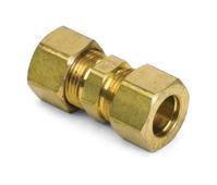
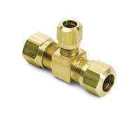
Inverted flare fittings are available in a range of body configurations. Straight connectors, elbows (45-degree and 90-degree), tee fittings, unions, and bulkhead connectors are all produced in inverted flare configurations. Each fitting configuration serves a specific routing or installation function while maintaining the same tube-end sealing geometry across all body styles. Inverted flare adapters also exist to transition between the inverted flare tube connection standard and other fitting standards such as NPT pipe threads, JIC 37-degree flare, ORFS (O-ring face seal), and metric tube connections.
The inverted flare fitting nut is a hex nut with an internal shoulder that bears against the back face of the inverted flare bead. The nut does not directly contact the sealing surface of the flare but instead provides the axial clamping force that drives the bead into the fitting body seat. Inverted flare nuts are specific to the inverted flare tube connection standard and are not interchangeable with SAE 45-degree flare nuts or JIC 37-degree flare nuts, despite the apparent similarity of these components when viewed externally.
Thread size identification is the most reliable method for distinguishing between nut types when the fitting body is not available for reference. SAE J512 inverted flare fitting nuts use SAE straight threads in specific size-to-thread combinations that differ from the thread specifications of SAE 45-degree flare fittings of the same nominal tube size. These differences are small enough that cross-threading is possible in some cases, leading to fitting damage that may not be immediately obvious but will prevent proper sealing.
Inverted flare fittings are produced in multiple materials, each with a distinctive appearance. Steel fittings are typically finished with zinc dichromate plating (producing a yellow or iridescent finish) or cadmium plating for corrosion resistance. Brass inverted flare fittings have the natural gold-yellow color of machined brass with no additional plating required for standard corrosion resistance. Stainless steel inverted flare fittings have the bright, slightly gray appearance of polished or brushed 316-grade stainless steel.
In automotive brake line applications, the most common materials encountered are steel tube with steel fitting nuts and either steel or brass fitting bodies. Brass inverted flare fittings are preferred for many service replacement applications because brass is easier to machine cleanly, does not corrode in the presence of glycol-based brake fluids, and provides a fitting seat hardness that is softer than the tube end material, allowing the tube end to form into the seat rather than the reverse.
The comparison between inverted flare fittings and standard flare nut fittings is one of the most practically important distinctions in fluid system design and service. The two systems appear similar to casual inspection, use similar components, and serve overlapping applications, but they are fundamentally incompatible with each other and selecting the wrong type for a given application produces connections that either leak immediately or fail after a short service period.
The most fundamental difference between inverted flare and standard flare connections is the geometry of the tube end and the mating fitting seat. As described above, the inverted flare produces a doubled-over bead that seats into an internal 42-degree cone in the fitting body. A standard SAE 45-degree flare produces a single-thickness outward cone on the tube end that mates with an external 45-degree seat on the fitting body nose.
These geometric differences mean that the fitting bodies of the two systems are different in their internal geometry, the tube end preparations are different in form, and the nuts (while often superficially similar in external dimensions) engage the tube ends differently. An inverted flare tube end placed in a standard flare fitting body will not seat correctly because the rounded bead profile does not match the conical 45-degree seat. A standard flare tube end in an inverted flare fitting body will similarly fail to seat correctly.
Inverted flare connections generally achieve higher pressure ratings than equivalent-size standard 45-degree flare connections, primarily due to the doubled-wall construction of the tube end. For 3/16-inch steel brake tubing, which is the most common brake line size in North American passenger vehicles, inverted flare connections are rated for continuous working pressures up to 3,000 psi in quality steel fittings. Standard single-thickness SAE 45-degree flare connections in the same tube size are typically rated to 2,000 to 2,500 psi, with the lower fatigue life of the single-thickness flare being the limiting factor under cyclic pressure loading.
Hydraulic inverted flare fittings used in industrial applications are rated to even higher working pressures depending on tube size and material. Hydraulic brake applications in commercial vehicles and heavy equipment routinely use inverted flare connections at system pressures exceeding 3,000 psi, relying on the superior fatigue resistance of the doubled flare construction to maintain seal integrity under sustained high-cycle pressure loading.
Standard SAE 45-degree flare fittings dominate in refrigeration and HVAC applications (where the softer copper and aluminum tubing involved benefits from the single-flare geometry) and in fuel gas distribution. Inverted flare fittings dominate in automotive hydraulic brake and fuel systems, power steering hydraulic circuits, and industrial hydraulic tubing where higher pressure ratings and superior vibration resistance are required.
JIC 37-degree fittings, which are sometimes confused with inverted flare fittings, are the dominant standard in industrial and aerospace hydraulic systems. JIC fittings use a 37-degree cone angle on the tube end (which is a single-thickness external flare, not an inverted flare) and mate with a 37-degree internal seat in the fitting body. JIC fittings are not interchangeable with inverted flare fittings despite the superficial similarity of their nut-and-ferrule construction.
| Feature | Inverted Flare Fitting | SAE 45-Degree Flare Fitting | JIC 37-Degree Flare Fitting |
|---|---|---|---|
| Tube End Form | Double-wall inverted bead | Single 45-degree outward cone | Single 37-degree outward cone |
| Seat Cone Angle | 42 degrees included (SAE J512) | 45 degrees included (SAE J512) | 74 degrees included (SAE J514) |
| Seal Location | Internal (inside fitting body) | External (nose of fitting body) | External (nose of fitting body) |
| Flare Wall Thickness | Double (folded back) | Single | Single |
| Typical Pressure Rating (3/16" tube) | Up to 3,000 psi | Up to 2,500 psi | Up to 3,000 psi (larger tube sizes) |
| Vibration Resistance | Excellent | Good | Very Good |
| Primary Applications | Automotive brake and fuel lines, hydraulics | HVAC, refrigeration, fuel gas | Industrial hydraulics, aerospace |
| Standard Reference | SAE J512 | SAE J512 | SAE J514 / ISO 8434-2 |
| Common Materials | Steel, brass, stainless steel | Brass, copper, aluminum | Steel, stainless steel, brass |
Correct installation of inverted flare fittings is both a skill and a process. The quality of the installation determines whether the connection will seal reliably for the full service life of the system or fail prematurely. Most inverted flare fitting leaks encountered in service are not the result of fitting defects or design shortcomings but of installation errors that are entirely preventable with the correct procedure, tools, and material preparation.
The most important tool in any inverted flare installation is the flaring tool itself. Inverted flare tube ends cannot be formed by hand or with improvised tooling; they require a purpose-made inverted flare tool that performs the two-stage forming operation (initial outward flare followed by inward rollback) in a controlled, repeatable manner. The main types of inverted flare forming tools are:
Supporting tools required for a complete inverted flare installation include a tube cutter (never a hacksaw, which leaves a non-perpendicular cut and raised burrs that prevent proper flare formation), a deburring tool or fine file for internal and external edge preparation, and correctly sized open-end or flare nut wrenches for tightening the fitting nuts. Using adjustable wrenches on inverted flare fitting nuts is a practice that damages the nut hex and creates the over-tightening that is one of the most common causes of fitting seat damage.
The following procedure applies to the installation of inverted flare fittings on steel or stainless steel tubing in automotive brake and hydraulic applications. The same general steps apply to brass inverted flare fittings used in fluid distribution systems, with minor variations in flaring force and tube projection distance based on material softness.
Inverted flare fitting sealing methods are primarily based on the metal-to-metal cone seat contact described throughout this article, but supplementary sealing approaches are used in specific applications where additional reliability or chemical compatibility is required.
Inverted flare fittings serve a wide range of applications across automotive, industrial, and commercial fluid system engineering. Their combination of high pressure rating, excellent vibration resistance, tool-free disassembly and reassembly, and all-metal construction without elastomeric seals makes them particularly well suited to critical fluid systems where seal reliability cannot be compromised and long-term service life is required.
The automotive brake system is by far the largest single application of inverted flare fittings. Every hard line connection in a conventional automotive hydraulic brake circuit uses inverted flare connections: the outlet ports of the master cylinder, the distribution block or proportioning valve connections, the hard line runs from front to rear of the vehicle, the connection points to the flexible brake hoses at wheel locations, and in some vehicles the connections at the ABS modulator block. A typical passenger car contains between eight and sixteen inverted flare connections in the brake hydraulic circuit.
Fuel system hard lines in many North American vehicles also use inverted flare connections at the fuel filter, fuel pressure regulator, and fuel rail inlet and return connections. The chemical resistance of the metal-to-metal seal to gasoline, diesel fuel, ethanol-blended fuels, and the various corrosion inhibitor packages used in modern fuels makes the inverted flare connection compatible with the full range of automotive fuel types without requiring compatibility verification of seal materials.
Power steering hydraulic systems in conventional (non-electric) power steering vehicles use inverted flare connections at the power steering pump outlet, the gear box or rack inlet and outlet, and the return line connections. Power steering systems operate at pressures up to 1,500 psi under full lock conditions, making the inverted flare pressure rating appropriate and its vibration resistance particularly valuable given the proximity of power steering lines to the engine and front suspension.
Automatic transmission oil cooler lines, which route hot transmission fluid from the transmission to the radiator cooler and back, use inverted flare connections at both the transmission case connections and the radiator connections. These lines carry relatively low pressure fluid but experience significant thermal cycling and vibration, conditions that favor the fatigue-resistant inverted flare connection over alternatives.
Hydraulic inverted flare fittings are used in a broad range of industrial and commercial equipment where tube connection reliability at moderate to high hydraulic pressures is required. Agricultural machinery, construction equipment hydraulic circuits, industrial press and clamping systems, and material handling equipment hydraulic circuits all represent application environments where hydraulic inverted flare fittings provide reliable, maintainable connections in demanding service conditions.
Inverted flare connectors are also used in compressed air distribution systems, hydraulic test equipment, and fluid sampling systems where the ability to make and break connections repeatedly without requiring tube end reformation is a significant operational advantage. In these applications, the inverted flare hose assembly, which combines a flexible hose with inverted flare end connections, provides the vibration isolation and routing flexibility of a hose assembly with the proven sealing reliability of the inverted flare connection at each end.
Correct size identification is fundamental to specifying and sourcing inverted flare fittings. The inverted flare fitting size chart follows SAE J512 standardized dimensions, with sizes designated by tube outside diameter in fractional inches. The most commonly encountered sizes in automotive and light industrial applications are presented in the table below, including the key dimensional parameters and standard thread specifications for each size.
| Tube OD (inches) | Tube OD (mm) | SAE Thread Size | Wrench Size (inches) | Typical Application | Max Working Pressure (steel) |
|---|---|---|---|---|---|
| 3/16 | 4.76 | 3/8-24 UNF | 9/16 | Automotive brake lines (primary) | 3,000 psi |
| 1/4 | 6.35 | 7/16-20 UNF | 5/8 | Fuel lines, power steering, light hydraulic | 2,500 psi |
| 5/16 | 7.94 | 1/2-20 UNF | 11/16 | Transmission cooling, return lines | 2,000 psi |
| 3/8 | 9.53 | 5/8-18 UNF | 3/4 | Power steering, hydraulic circuits | 1,800 psi |
| 1/2 | 12.70 | 3/4-16 UNF | 7/8 | Industrial hydraulic, larger flow systems | 1,500 psi |
| 5/8 | 15.88 | 7/8-14 UNF | 1-1/16 | High-flow hydraulic, commercial vehicle | 1,200 psi |
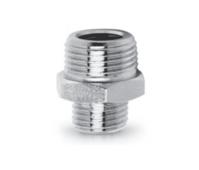
Inverted flare adapters bridge the gap between the inverted flare tube connection standard and other connection standards that appear in the same fluid system. They are necessary whenever an inverted flare tube line must connect to a component with a different port standard, which is a routine situation in automotive and industrial fluid system repair and modification. Common inverted flare adapter configurations include:
Leaks in inverted flare fitting connections are almost always preventable. Unlike some other fitting types where leak prevention is a matter of applying the right sealant or achieving the right torque, inverted flare leak prevention is fundamentally a matter of correct preparation and assembly practice. The following leak prevention guidelines represent the aggregated best practices of professional hydraulic and brake system technicians.
The majority of inverted flare connection leaks originate in preparation errors that are invisible after assembly but prevent the metal-to-metal seal from achieving intimate contact. Addressing every preparation step consciously eliminates this cause of failure:
When an existing inverted flare connection develops a leak in service, the correct diagnostic and repair approach depends on the nature and location of the leak. Attempting to stop a leaking inverted flare fitting by further tightening the nut is the most common and most damaging incorrect response to a leak. In most cases, additional tightening beyond the specified torque damages the fitting seat and the flare bead further, making the leak worse rather than better, and requiring replacement of both the tube end and the fitting body.
The correct response to an inverted flare connection leak is disassembly, inspection of both the flare bead and the fitting body seat, identification of the source of the sealing failure, and appropriate corrective action. If the flare bead shows cracking, deformation, or non-uniform geometry, the tube end must be cut off and a new flare formed. If the fitting body seat shows scoring, pitting, or deformation, the fitting body must be replaced. In either case, the repair must address the root cause of the sealing failure, not attempt to compensate for it through over-tightening or sealant application.
Thread leaks, which manifest as seepage along the fitting nut threads rather than from the tube-to-seat interface, indicate either damaged threads, incorrect thread engagement, or missing thread sealant on the fitting body's external port threads where NPT connection is used. These are addressed by cleaning and inspecting the threads, replacing damaged components, and applying appropriate thread sealant to the NPT port threads where required by the fitting design.
Inverted flare fittings are a sophisticated, reliable, and extensively proven tube connection system that delivers superior performance in high-pressure, high-vibration applications when correctly specified, properly installed, and appropriately maintained. The knowledge of what they are, what they look like, how they compare to alternatives, and how to install and maintain them correctly transforms the inverted flare fitting from a mysterious component into a completely manageable element of professional fluid system work.
Add:Xingzhong Road DianKou Town Zhuji City Zhejiang Province China
Mob: 0086-139 8951 3573
Tel: 0086-575-87560582
Fax: 0086-575-87560582
E-mail:[email protected]

 英语
英语 西班牙语
西班牙语