24Hours Tel
0086-139 8951 3573
Free Inqiry
E-mail:[email protected]
24Hours Tel
0086-139 8951 3573
Free Inqiry
E-mail:[email protected]
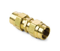
For high pressure hydraulic, refrigerant, and fuel systems, the 37-degree SAE flare fitting and the Inverted Flare fitting are the two most widely specified connection types, with selection determined by the system medium, operating pressure ceiling, and the assembly access constraints of the installation environment. The 37-degree SAE flare is the standard for hydraulic lines and high-pressure fuel systems rated up to 3,000 PSI, while the Inverted Flare is the dominant standard in automotive brake hydraulics and fuel delivery lines where the reversed cone geometry provides a more compact, vibration-resistant assembly in tight under-vehicle routing conditions. Selecting the wrong fitting type for a high pressure application does not simply produce a leaking joint — it can produce a catastrophic connection failure with no warning, because the wrong cone angle prevents the metal-to-metal seal from forming correctly even when the fitting appears to be tightened securely.
This guide covers all principal flare fitting types in commercial use, their pressure ratings, material options including brass fittings, their most appropriate application environments, and the specific factors that should drive selection decisions when working with high pressure fluid and gas systems.
All flare fittings share the same fundamental sealing principle: a conical flare formed at the end of a metal tube is pressed against a matching conical seat in the fitting body by the compressive force of a flare nut tightened around the tube. As the nut is tightened, the two cone surfaces are driven together under increasing contact pressure, deforming the softer surface material slightly to fill microscopic surface irregularities and creating a continuous metal-to-metal seal line that is both leak-tight and mechanically robust enough to resist the pressure of the contained fluid or gas.
The angle of the flare cone is the critical geometric variable that differentiates the major flare fitting types. Even a difference of 8 degrees between the tube flare angle and the fitting seat angle produces a line contact rather than surface contact between the two cone surfaces, concentrating stress on a narrow ring rather than distributing it across the full cone face. This mismatched contact geometry produces a joint that may hold pressure initially but will fail progressively under vibration, thermal cycling, and pressure pulsation as the narrow contact ring embeds and the seal degrades. This is why different flare fitting types cannot be interchanged even when they appear to fit together physically.
The quality of the flare formed at the tube end is as critical to joint reliability as the quality of the fitting itself. A flare that is eccentric, cracked, under-formed, or formed to the wrong angle will produce an unreliable seal regardless of how precisely the fitting body is machined. Correct flaring requires a tube that is cut squarely without burrs, annealed if it has been work-hardened by cold bending close to the flare location, and formed in a properly sized flaring tool block with a cone mandrel matched to the required flare angle.
Common flaring errors and their consequences include:
Four flare cone angles account for the vast majority of flare fitting applications in hydraulic, refrigeration, automotive, and industrial piping systems worldwide. Each is standardized under specific national or international standards that govern the cone angle, tube size range, thread form, and dimensional tolerances of the mating components.
The 37-degree SAE flare, governed by SAE J514 and ISO 8434-2, is the foundational flare fitting standard for hydraulic power systems, industrial machinery, and high-pressure fuel delivery. The 37-degree half-angle produces a relatively shallow cone that distributes assembly load across a large contact area, giving this design its high pressure capability. 37-degree SAE flare fittings in steel are rated for working pressures of up to 3,000 PSI in larger tube sizes and up to 5,000 PSI in smaller tube sizes below 1/4 inch OD, making them the standard connection for mobile hydraulic equipment including agricultural machinery, construction equipment, and industrial press and lift systems.
The 37-degree SAE flare system uses JIC (Joint Industry Council) thread specifications, with straight (UN/UNF) threads on both the nut and the fitting body's male thread. The straight thread engagement does not contribute to sealing; all sealing is accomplished by the cone-to-cone metal contact. 37-degree brass fittings in this geometry are widely used in lower-pressure hydraulic and fuel system applications where the excellent machinability and corrosion resistance of brass make it preferable to steel, typically for systems operating below 1,500 PSI with non-petroleum-based fluids.
The 45-degree flare, governed by SAE J513 and widely used across the HVAC and refrigeration industry, uses a steeper cone angle that creates a stronger bite into the tube flare face under assembly torque. This steeper angle is well-suited to the relatively thin-walled copper tubing that dominates refrigeration and air conditioning system construction, where the deep-biting 45-degree cone creates a reliable seal even when the copper tube has some softness variation from the annealing process.
45-degree flare connections in refrigeration are rated for working pressures of 200 to 700 PSI depending on tube diameter and wall thickness, which covers the operating pressure range of R-410A, R-22, and R-134a refrigerant systems used in residential and light commercial HVAC equipment. Brass fittings with 45-degree seats are the standard fitting material for copper refrigerant tubing connections because brass machines cleanly to the required seat geometry, resists the mild corrosive effects of refrigerant and refrigeration oil mixtures, and is soft enough relative to the copper tube to allow the tube flare to embed slightly into the seat under assembly, improving seal conformance.
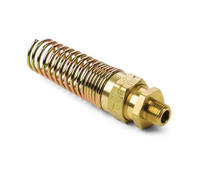
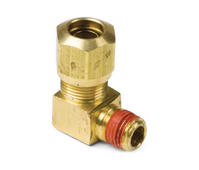
The Inverted Flare fitting, also called the double flare or inverted double flare in its most common implementation, is the standard connection method for automotive brake hydraulic circuits and OEM fuel delivery lines. Unlike the standard (outward) flare where the tube end is flared outward into a cone that contacts the fitting seat on its outer face, the Inverted Flare folds the tube end back on itself to create a double-wall section that is then formed into an inverted cone that seats inside the fitting body rather than outside it.
This inverted geometry has two important consequences. First, the double-wall section at the flare is approximately twice the wall thickness of the original tube, making the Inverted Flare joint significantly more resistant to pressure-induced fatigue cracking than a single-wall 45-degree flare on the same tube. Second, the flare nut compresses around the outside of the tube rather than threading onto the fitting body, creating a more compact assembly profile that routes more easily through the tight spaces under vehicles and within engine compartments where automotive brake and fuel lines are routed. Inverted Flare connections in SAE 1010 cold-drawn steel tubing are the specification mandated by most automotive OEMs for brake hydraulic lines, rated for operating pressures of 1,500 to 2,000 PSI at continuous operating temperatures up to 150°C.
Brass fittings are commonly used for Inverted Flare connections in non-automotive applications including propane and natural gas distribution systems, where the combination of the Inverted Flare's vibration resistance and brass's corrosion resistance to gas moisture and atmospheric exposure creates a reliable long-term connection at appliance connection points. The 45-degree Inverted Flare geometry used in automotive brake applications should not be confused with the 37-degree Inverted Flare used in some industrial gas applications; the two are dimensionally incompatible and should never be intermixed.
European industrial machinery and hydraulic systems use the DIN 2353 (ISO 8434-1) metric tube fitting system, which incorporates a 24-degree cone angle in its flare-type variant. The 24-degree DIN fitting is used in hydraulic systems on European agricultural, construction, and material handling equipment and is dimensionally distinct from both the 37-degree SAE and 45-degree refrigeration flares in every dimension including thread form, tube OD range, and cone geometry.
DIN 24-degree metric flare fittings are rated for pressures up to 630 bar (approximately 9,100 PSI) in the smallest tube sizes, making them the highest-rated of the common flare fitting standards. They are manufactured primarily in carbon steel and stainless steel for hydraulic applications, with brass versions available for pneumatic and lower-pressure fluid system applications where metric tube sizing and DIN threading are required.
| Flare Type | Cone Half Angle | Governing Standard | Typical Pressure Rating | Primary Application | Common Material |
|---|---|---|---|---|---|
| 37-Degree SAE / JIC | 37 degrees | SAE J514 / ISO 8434-2 | Up to 5,000 PSI | Hydraulic systems, high-pressure fuel | Steel, brass fittings, stainless |
| 45-Degree SAE | 45 degrees | SAE J513 | 200 to 700 PSI | HVAC, refrigeration, low-pressure plumbing | Brass fittings, aluminum |
| Inverted Flare (double wall) | 45 degrees inverted | SAE J1390 / ISO 1817 | 1,500 to 2,000 PSI | Automotive brake hydraulics, fuel lines, gas appliances | Steel, brass fittings |
| 24-Degree DIN Metric | 24 degrees | DIN 2353 / ISO 8434-1 | Up to 9,100 PSI (small sizes) | European hydraulic machinery, pneumatics | Steel, stainless, brass fittings |
Brass fittings are the material of choice for a large proportion of flare fitting applications, and understanding exactly where their properties are advantageous versus where they impose limitations determines whether brass is the right specification for a given system.
Brass (typically C36000 free-machining brass or C37700 forging brass for fitting bodies) offers a combination of properties that make it particularly well-suited to flare fitting manufacture and performance:
Despite their many advantages, brass fittings have specific limitations that exclude them from certain high pressure flare applications:
Standard C36000 free-machining brass contains approximately 3 percent lead as a machinability enhancer, which is acceptable for most industrial and HVAC applications but is restricted in potable water systems by legislation in several jurisdictions. In the United States, the Reduction of Lead in Drinking Water Act (effective 2014) limits the weighted average lead content of brass fittings in contact with potable water to 0.25 percent, effectively requiring low-lead alloys such as C69300 (bismuth-free low-lead brass) or bismuth-selenide enhanced alloys for all flare fittings used in residential and commercial water supply systems. Products carrying NSF/ANSI 61 and NSF 372 certification have been tested and confirmed to meet these lead content requirements.
The Inverted Flare merits more detailed treatment than other flare types because its construction is significantly different from standard outward flares, its assembly requires a specific two-stage forming tool that is different from standard flaring tools, and its failure modes when incorrectly assembled or when the wrong fitting type is substituted are particularly severe given its dominant use in automotive brake hydraulics.
Forming an Inverted Flare on steel brake line tubing requires a double-flare tool set consisting of a flaring block, a first-stage adapter (the bubble tool), and a second-stage flaring cone. The process proceeds in two steps:
The result is a double-wall flare with an inverted 45-degree cone that fits inside the matching seat in the Inverted Flare fitting body, with the nut threading over the outside of the tube and bearing against the back face of the double-wall section. A correctly formed Inverted Flare on SAE 1010 steel brake tubing should show no cracks on the cone face or the folded inner surface, should have uniform wall thickness around the full circumference of the cone, and should sit flush against the fitting body seat without rocking when pressed in by hand before the nut is engaged.
A common and dangerous error in brake system repair is attempting to connect a standard outward 45-degree flare to an Inverted Flare fitting body. The fitting nut may thread on, and the joint may appear assembled, but the sealing geometries are fundamentally incompatible: the outward flare presents a convex cone face to the Inverted Flare's concave seat, producing only a small-diameter ring contact near the outer edge of the cone rather than the full face contact of a correctly matched Inverted Flare. Under brake system operating pressure, this mismatched joint will either leak immediately during system pressurization or will seal briefly and then fail catastrophically under the first hard braking event.
Visual identification of Inverted Flare fittings requires looking into the end of the fitting body: an Inverted Flare fitting has a concave (inward-pointing) seat that will accept the Inverted Flare cone, whereas a standard 45-degree flare fitting has a convex or flat seat that the outward flare rests against on its inner face. Brake fittings are also commonly identified by the metric thread sizes that distinguish them from non-brake automotive fittings.
In residential and commercial gas appliance connection applications, brass Inverted Flare fittings in the 45-degree geometry are specified for connecting flexible gas connectors to both the appliance inlet and the wall or floor outlet. The Inverted Flare geometry is preferred over the standard outward flare in this application because it creates a more secure nut retention: the flare nut seats against a shoulder on the fitting body rather than simply capturing the tube flare against the seat, making it more resistant to the vibration that occurs in service environments where gas appliances such as dryers and ranges are moved for cleaning and maintenance.
Brass Inverted Flare fittings for gas service must carry appropriate approval markings including CGA (Compressed Gas Association) listing and CSA or AGA approval confirming that they have been tested for gas tightness and structural integrity under the cycle pressures and temperature ranges specified for residential gas distribution systems. Using non-listed brass fittings in gas appliance connections is a code violation in most jurisdictions and creates liability exposure for the installer regardless of the fitting's apparent quality.
With the principal flare fitting types and their characteristics understood, the selection process for a specific high pressure application can be structured around five sequential decision criteria that progressively narrow the field to the correct fitting specification.
In most regulated applications, the fitting type is specified by the system design standard rather than by the installer's preference. Automotive brake hydraulic systems are governed by FMVSS 116 and SAE J1290, which mandate double-wall Inverted Flare connections for brake line terminations. European hydraulic systems are designed to ISO 4413 and typically use DIN 2353 metric tube fittings. Refrigeration systems are designed to ASHRAE 15 and typically specify 45-degree flare connections on copper tube in the applicable size range. Following the governing standard is the correct first step and eliminates most ambiguity about which flare type to use.
The selected fitting type and material must have a published working pressure rating that meets or exceeds the maximum allowable working pressure (MAWP) of the system, inclusive of pressure spikes from pump pulsation, water hammer, and pressure relief valve set points. Apply a minimum safety factor of 4:1 between the fitting's rated burst pressure and the system operating pressure for critical fluid power and brake hydraulic applications, which is consistent with the design safety factors in ISO 4413 and SAE J514. If the required operating pressure exceeds the brass fitting rating, upgrade to carbon steel or stainless steel in the same fitting geometry rather than switching to a different flare type.
Confirm that the fitting material is compatible with the system fluid across the full operating temperature range. Key incompatibilities to check include brass with ammonia, zinc-based alloys with strong acids or alkalis, and carbon steel with aggressive water or salt solutions. For petroleum-based hydraulic fluids, water-glycol hydraulic fluids, and hydrocarbon refrigerants, brass fittings are compatible across the full temperature range appropriate for brass (minus 40°C to plus 120°C for standard brass; minus 60°C to plus 150°C for dezincification-resistant grades).
The physical environment in which the fitting will be assembled and the frequency with which the connection may need to be disconnected for maintenance affect the optimal fitting type selection. Locations where full rotation access for a wrench is limited favor fitting designs that can be assembled with a fixed body and rotating nut, which all standard flare fitting types accommodate. Applications requiring frequent disconnection for filter or component changes favor the 37-degree JIC and DIN 24-degree types, which are fully reusable through multiple assembly and disassembly cycles without requiring tube re-forming. The Inverted Flare in steel brake line is the least maintenance-friendly flare type, as disassembly typically requires cutting the line and re-forming the flare, which is why it is specified only where its vibration resistance and compact profile justify the maintenance trade-off.
Flare fittings use multiple thread forms that are not interchangeable despite appearing similar in size. SAE J514 37-degree fittings use UN/UNF straight threads with specific pitch diameters defined in the SAE standard. Brake system Inverted Flare fittings use metric threads (M10 x 1.0 and M12 x 1.0 are the two most common in automotive applications) that will not engage with SAE UN/UNF threads. DIN 24-degree fittings use metric threads per DIN 2353. Before ordering replacement or extension fittings for an existing system, always identify the thread form and pitch by measurement or by consulting the system manufacturer's parts documentation, as visual inspection alone cannot reliably distinguish between different thread forms of similar pitch.
| System Type | Recommended Flare Type | Recommended Material | Governing Standard | Key Selection Consideration |
|---|---|---|---|---|
| Hydraulic power (up to 3,000 PSI) | 37-Degree SAE / JIC | Steel; brass fittings below 1,500 PSI | SAE J514 | Reusability and pressure rating |
| HVAC and refrigeration | 45-Degree SAE | Brass fittings (copper tube compatibility) | SAE J513 | Refrigerant compatibility with brass |
| Automotive brake hydraulics | Inverted Flare (double wall) | Steel (OEM); brass fittings for body fittings | SAE J1390 / FMVSS 116 | Mandatory standard; no substitution |
| Gas appliance connections | Inverted Flare (45 degree) | Brass fittings (CGA listed) | CGA / CSA / AGA | Listed product requirement for code compliance |
| European hydraulic machinery | 24-Degree DIN Metric | Steel; stainless; brass fittings for pneumatics | DIN 2353 / ISO 8434-1 | Metric tube OD sizing and DIN thread form |
Correct assembly torque is the final and frequently overlooked variable that determines whether a correctly specified and correctly formed flare fitting joint will perform reliably throughout its service life. Both under-torquing and over-torquing flare connections produce unreliable joints: under-torquing leaves the cone-to-cone contact pressure below the minimum needed to seal against system pressure, while over-torquing plastically deforms the tube flare beyond its elastic range, distorting the cone geometry and potentially cracking the flare material.
SAE J514 specifies assembly torques for 37-degree JIC fittings ranging from 9 Nm (80 inch-pounds) for 3/16 inch tube to 135 Nm (100 foot-pounds) for 1-1/4 inch tube, and these values should be applied with a calibrated torque wrench for critical hydraulic and pressure system assembly rather than estimated by feel. For brass fittings, apply approximately 75 to 85 percent of the steel specification torque to avoid over-stressing the softer brass nut threads at equivalent clamp loads.
After assembly, all high pressure flare fitting connections should be pressure tested at 1.5 times the system maximum allowable working pressure before being put into service, with all connections inspected for leakage using an appropriate leak detection method: soap solution for gas systems, fluorescent dye for hydraulic fluid systems, or nitrogen pressure decay testing for clean systems where fluid contamination of the leak detection medium is unacceptable. A joint that passes this initial pressure test and shows no visible distortion of the flare nut or tube should provide leak-free service for the full design life of the tubing system when the correct fitting type, material, and assembly procedure have been applied.
Add:Xingzhong Road DianKou Town Zhuji City Zhejiang Province China
Mob: 0086-139 8951 3573
Tel: 0086-575-87560582
Fax: 0086-575-87560582
E-mail:[email protected]

 英语
英语 西班牙语
西班牙语