24Hours Tel
0086-139 8951 3573
Free Inqiry
E-mail:[email protected]
24Hours Tel
0086-139 8951 3573
Free Inqiry
E-mail:[email protected]
Every plant has that one machine. It knocks loudly when the directional valve shifts, weeps oil from a fitting overnight, and blows a hose at the worst possible moment. A maintenance supervisor once described the same pattern on three machines: a metallic bang, a hairline crack in a brass elbow, two hose failures at the crimp, and cylinder seals leaking within weeks. None of the parts were defective. All three machines were being damaged by hydraulic shock.
Hydraulic shock, also called water hammer, is a pressure surge created when a moving fluid is forced to stop or change direction suddenly. The kinetic energy of the fluid column converts into pressure energy almost instantly. In a system that normally runs at 210 bar (3,000 psi), a single surge can produce spikes well above twice the working pressure. The exact peak depends on flow velocity, line length, and how fast the flow is interrupted.
The mechanism is well documented. When a valve closes in front of a moving column of oil, the fluid nearest the valve stops first. The fluid behind it keeps moving, compresses, and sends a pressure wave back up the line at the speed of sound in that fluid. For mineral hydraulic oil, the wave speed is typically 1,300 to 1,500 meters per second. The pressure rise can be estimated with Joukowsky's equation, which states that the pressure increase equals the fluid density multiplied by the wave speed and the change in flow velocity. Even a velocity change of one meter per second creates a measurable spike.
In extreme cases, the pressure can drop below the vapor pressure of the oil, allowing the fluid column to separate. When the column rejoins, the impact is often more violent than the original surge. Hydraulic shock appears in many forms: the hammering of a household water pipe, the thud in a fire-suppression line, and the clatter in a truck air brake system. The physics is the same everywhere. Only the scale changes.
Uncontrolled hydraulic shock does more than make noise. It attacks every component in the pressure path, and the damage accumulates with every cycle. The table below summarizes the most common failure patterns seen in the field.
| Component | Damage mechanism | Typical evidence |
|---|---|---|
| Hoses | Wire braid fatigue and inner tube rupture near the crimp | Bulges, weeping at the fitting, sudden burst under pressure |
| Brass fittings | Hairline cracks at hex corners and thread roots | Oil mist around the fitting, drips after shutdown, visible cracks under inspection |
| Seals and cylinders | Seal extrusion, rod scoring, piston seal failure | Creeping cylinders, external leaks, slow pressure decay |
| Pumps and valves | Spool wear, cavitation pitting, bearing damage | Slower response, rising oil temperature, whine or knock |
| Sensors and gauges | Diaphragm fatigue, zero drift, internal damage | Erratic readings, premature gauge failure |
The direct cost is downtime. A burst hose stops a production line for an hour and creates a safety hazard. A cracked fitting leaks expensive oil onto the floor, and every leak invites contamination. When the damaged component is brass, small particles can break away and circulate through the system, scoring pump plates and valve bores. The repair bill then goes far beyond replacing one fitting.
The hidden cost is harder to measure. Every surge event works the components like a fatigue test machine. A fitting that looks fine after ten thousand cycles may crack on the ten-thousand-and-first, and the failure almost always arrives at the worst time. Tracking surge-related failures over a year usually shows that the money spent on prevention is small compared with the cost of repairs, oil, and lost production.
Hydraulic shock usually results from a combination of design choices and operating conditions rather than one mistake. The most frequent contributors are:
Identify which of these factors apply before choosing a fix. A solution that cures a valve-induced surge may do nothing for a pump-start transient, and most systems need more than one correction.
System-level changes give the best return because they address the source of the surge instead of the symptom. The measures below are the most widely used in machine design and retrofits.
The simplest way to reduce shock is to give the fluid more time to decelerate. Directional valves with adjustable spool travel or pilot chokes shift in 50 to 150 milliseconds instead of 15 to 20. That delay changes an abrupt stop into gradual deceleration, which reduces the pressure spike proportionally. Proportional valves can achieve the same effect with ramp settings. In retrofit situations, adding pilot chokes is inexpensive and often solves chronic hose failures without changing the valve.
An accumulator acts as a shock absorber for the circuit. A properly sized unit placed close to the surge source absorbs the pressure wave and releases the energy slowly. Sizing must consider the worst-case surge, not the average flow, because an undersized accumulator compresses fully and then behaves like a rigid wall.
In cylinder circuits, crossport relief valves let the fluid displaced by a stopping load return to tank instead of spiking against the valve. This is the most effective protection for heavy loads moving at speed, such as press platens, forklift masts, and excavator booms.
Air in hydraulic fluid is compressible and stores energy. When a pressure wave hits an air pocket, the pocket collapses and releases a secondary shock that can be more violent than the original. Bleed the system after every line replacement and watch for foam in the reservoir as a sign of leaky suction lines.
Long, unsupported runs and sharp bends amplify surge effects. Shorten lines, use larger diameters, and avoid sudden changes in cross-section. Mount accumulators and shock suppressors as close to the accelerating component as the layout allows.
Even a well-designed circuit still produces transient peaks. Component selection decides whether the system survives them or fails in service. Hose and fitting ratings matter as much as the system design.
Every hydraulic hose carries two pressure numbers. Working pressure is the steady-state rating; impulse rating reflects how many pressure cycles the hose survives at a defined peak. Many crimp-end failures occur because the impulse rating was ignored. A hose selected on working pressure alone may pass the first test and still fail after thousands of surge cycles. For this reason, experienced buyers specify hydraulic hose fittings with matched impulse ratings rather than mixing hose brands and end fittings arbitrarily. The assembly is only as strong as its weakest element, and the fitting is usually that element.
A pressure spike works on a fitting like a hammer on a chisel. Thread roots and hex corners become stress concentration points. Brass is widely used because it dampens vibration, resists corrosion, and machines cleanly, but brass is only as good as the alloy and the manufacturing process. Fittings with consistent wall thickness, properly cut threads, and clean geometry survive repeated surges far better than parts with porosity or thin sections. Standards matter for the same reason. SAE 45-degree flare, JIC, BSPP, BSPT, NPT, and metric thread forms differ in sealing principle, seating angle, and tolerance. Mixing them is one of the most common causes of leaks and fitting fatigue. A complete range of hydraulic adapters and connectors in consistent standards removes the temptation to force mismatched threads. For tubing connections that must endure vibration and repeated pressure peaks, brass compression male connectors provide a reliable metal-to-metal grip without requiring flaring tools.
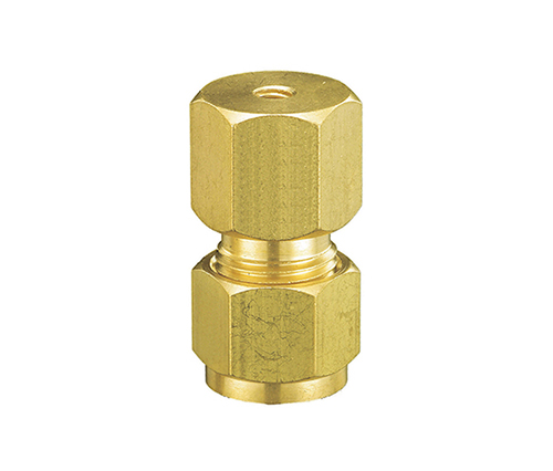 OEM 1/4 NPT Compression Double Male Connector Manufacturers, Factory - Zhejiang Zhejiang Qinwei Fluid Technology Co., Ltd is China 1/4 NPT Compression Double Male Connector Suppliers and Manufacturers, As OEM 1/4 NPT ...View Product →
Every connection style fits a duty class. Flare fittings suit high-pressure lines where predictable torque is available. Compression fittings handle instrumentation and medium-pressure tubing. Push-on fittings are fast to assemble and work well on return lines, where a push-on hose barb to male pipe fitting eliminates clamps while keeping assembly time short. In commercial vehicle air brake systems, where a pressure transient follows every brake application, validated male straight tee air brake connectors are manufactured to DOT specifications and stamped accordingly. Fleet maintenance teams also rely on DOT-approved air brake fittings to keep replacement parts traceable to a known standard.
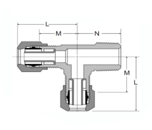 OEM 1471# Air Brake Fitting Male Run Tee Manufacturers, Factory - Zhejiang QinwZhejiang Qinwei Fluid Technology Co., Ltd is China 1471# Air Brake Fitting Male Run Tee Suppliers and Manufacturers, As OEM 1471# Air B...View Product →
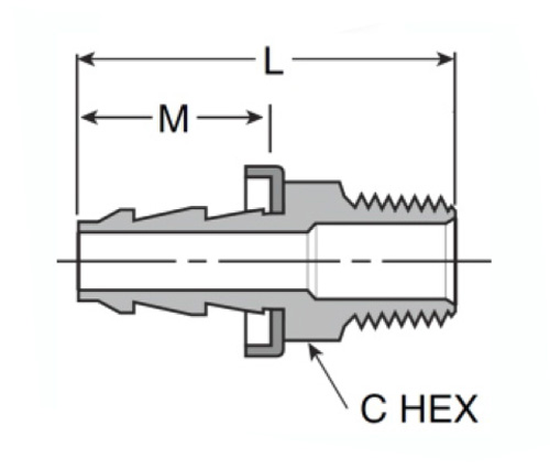 OEM 272 Push-on Hose Barb to Male Pipe Manufacturers, Factory - Zhejiang Qinwei Zhejiang Qinwei Fluid Technology Co., Ltd is China 272 Push-on Hose Barb to Male Pipe Suppliers and Manufacturers, As OEM 272 Push-on Hos...View Product →
Installation is part of the defense. Over-tightening a brass fitting distorts the threads and creates stress concentrations that crack under surge pressure. Under-tightening leaves the connection loose. Follow the manufacturer's torque recommendation and use the correct sealing method: thread sealant for tapered threads, O-rings or bonded washers for parallel threads, and a clean, undamaged surface for flare seats.
Use this list during design review, after a failure, or as part of a scheduled maintenance audit. Work through it in order, because causes and fixes are often connected.
Hydraulic shock is a physics problem that can be managed with engineering. Slow the flow transition, absorb the wave, and select components rated for real operating conditions. When those three things are done consistently, the bang disappears and replacement intervals lengthen. The same principles keep a clean-running system reliable even as duty demands rise.
Add:Xingzhong Road DianKou Town Zhuji City Zhejiang Province China
Mob: 0086-139 8951 3573
Tel: 0086-575-87560582
Fax: 0086-575-87560582
E-mail:[email protected]

 英语
英语 西班牙语
西班牙语