24Hours Tel
0086-139 8951 3573
Free Inqiry
E-mail:[email protected]
24Hours Tel
0086-139 8951 3573
Free Inqiry
E-mail:[email protected]
The selection of a mechanical connection method for tubing systems is a critical decision that influences the safety, durability, and efficiency of fluid and gas distribution. Two of the most prevalent systems in the world of mechanical engineering are flare fittings and compression fittings. Both systems are designed to create a leak-proof seal between two sections of tubing or between a tube and a component such as a valve or a manifold. However, the choice between them is rarely a matter of simple preference. It is instead a complex calculation based on the operating pressure of the system, the vibration levels of the environment, the specific medium being transported, and the skill level of the technician performing the installation. To understand which is better for a given scenario, one must look closely at the underlying physics of how each fitting achieves its seal and how the materials of the tubing and the fitting interact over thousands of hours of operation.
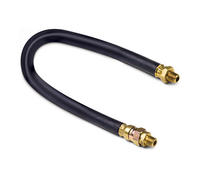
Flare fittings represent one of the most robust methods for connecting metal tubing, particularly in high-pressure or high-vibration environments. The fundamental principle of a flare fitting is the mechanical deformation of the tubing end into a conical shape, which is then clamped between a threaded fitting body and a flare nut. This design creates a metal-to-metal seal that relies on the precise alignment of the flared tube surface and the machined nose of the fitting. Because the seal is formed by the tubing material itself, there are no additional components like gaskets or washers that can perish or fail over time.
The structural integrity of a flare fitting is rooted in the surface area of the contact point. When the flare nut is tightened, it exerts a massive amount of axial force that pulls the flared end of the tube against the mating surface of the fitting body. This compression creates a high-pressure contact zone that is capable of containing volatile gases and high-pressure hydraulic fluids. The success of this seal depends heavily on the quality of the flare, which must be symmetrical and free of any scoring or burrs that could provide a pathway for leaks.
The process of flaring the end of a tube is a form of cold working the metal. When a technician uses a flaring tool, they are forcing the metal to expand outward at a specific angle, which is typically forty-five degrees for automotive and plumbing applications or thirty-seven degrees for industrial and aerospace applications. This expansion increases the grain density at the flare, making the contact surface slightly harder than the rest of the tubing. This localized hardening is beneficial because it allows the flare to resist deformation when the nut is tightened to high torque specifications.
However, this cold forming process also means that the selection of the tubing material is vital. Flare fittings are most effective when used with annealed or soft-tempered tubing, such as soft copper, aluminum, or certain grades of stainless steel. If the tubing is too hard, it may crack or split during the flaring process, which would compromise the seal before the fitting is even assembled. The thickness of the tube wall also plays a significant role, as thicker walls require more force to flare but provide a larger surface area for the seal, which is why flare fittings are the standard in heavy-duty refrigeration and high-pressure brake systems.
The angle of the flare is the most critical dimension in this system, and it is strictly regulated by various engineering standards. The Society of Automotive Engineers, or SAE, mandates a forty-five-degree flare for most domestic applications. This angle was chosen because it provides a good balance between ease of flaring and the amount of clamping force required to hold the seal. In contrast, the Joint Industry Council, or JIC, and the military standards often utilize a thirty-seven-degree flare.
The thirty-seven-degree angle is preferred in hydraulic systems where pressures are significantly higher and vibration is more intense. The steeper angle allows for a deeper engagement between the tube and the fitting, which improves the resistance to pull-out forces. Mixing these two angles is a common error in the field that inevitably leads to failure, as a forty-five-degree flare nut cannot apply even pressure to a thirty-seven-degree fitting. This highlights why flare fittings require a higher degree of technical knowledge and specialized tooling compared to simpler connection methods.
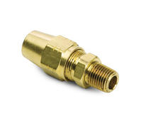
Compression fittings offer a different approach to fluid connection that prioritizes speed and ease of installation without the need for specialized tube-forming tools. A compression fitting consists of three distinct parts, which are the fitting body, the nut, and the compression ring or ferrule. Unlike the flare system where the tube itself is reshaped, the compression system relies on the ferrule to do the work. As the nut is tightened onto the body, it forces the ferrule to slide along the tube and eventually compress inward, biting into the outer surface of the tubing to create a seal.
The simplicity of this design makes compression fittings the preferred choice for a wide variety of plumbing and low-to-medium pressure industrial tasks. Because no flaring tool is required, these fittings can be installed in tight spaces where swinging a flare handle would be impossible. The seal is formed at two points, where the ferrule meets the fitting body and where the ferrule grips the tube. This dual-point contact provides a reliable barrier against leaks in systems that transport water, oil, or low-pressure air.
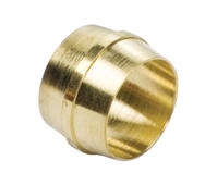
The ferrule is the most engineered component in a compression fitting. In high-quality systems, the ferrule is made of a material that is slightly softer than the fitting body but harder than the tubing. This ensures that when the nut is tightened, the ferrule deforms just enough to create a gas-tight seal against the body while simultaneously digging into the tubing wall to provide mechanical grip. In some advanced industrial designs, a twin-ferrule system is used. The front ferrule provides the pressure seal, while the back ferrule provides the mechanical grip that prevents the tube from blowing out under pressure.
This biting action is what gives compression fittings their name and their strength. However, it also means that the tubing must have a consistent outer diameter and a smooth surface finish. If the tubing has deep scratches or is out-of-round, the ferrule will not be able to seat properly, leading to slow leaks. Furthermore, because the ferrule permanently deforms the tube by biting into it, these fittings are generally not considered as reusable as flare fittings. Once a compression fitting is disassembled, the ferrule remains permanently swaged onto the tube, often requiring the technician to cut the tube and start fresh if a new connection is needed.
Compression fittings are highly sensitive to the hardness of the tubing material. If the tubing is too soft, such as thin-walled plastic or very soft lead, the ferrule can actually crush the tube rather than biting into it. This can lead to a restriction in flow or a complete collapse of the tubing wall, which results in a catastrophic failure of the connection. To prevent this, technicians often use internal support inserts or sleeves when using compression fittings with plastic tubing, which provide the necessary internal resistance for the ferrule to grip against.
On the other end of the spectrum, if the tubing is too hard, such as heavy-walled stainless steel or titanium, the ferrule may fail to bite into the surface. This creates a risk that the tube will simply slide out of the fitting once the system is pressurized. Professional installers must ensure that the ferrule material is compatible with the tubing hardness to achieve a successful mechanical bond. This material compatibility is a foundational aspect of compression fitting engineering and is why manufacturers provide specific guidelines for torque and material combinations.
When comparing the two systems, the decision often comes down to the environment in which the fitting will reside. Flare fittings are generally considered superior for applications involving high-pressure gases and intense mechanical vibration. The reason for this lies in the way the seal is supported. In a flare fitting, the flared end of the tube is physically trapped between the nut and the body. Even if the system vibrates, the flare cannot easily back out or move, and the metal-to-metal contact remains constant.
In contrast, compression fittings are more susceptible to vibration over long periods. Because the ferrule relies on a mechanical bite, high-frequency vibrations can eventually cause the ferrule to loosen its grip or create microscopic gaps between the ferrule and the tube. While this is rarely an issue in a stationary residential plumbing system, it is a major concern in automotive engines, industrial machinery, and aerospace fluid lines. This is why you will almost always find flare fittings on hydraulic brake lines and refrigerant lines, where the consequences of a leak or a blowout are much more severe.
|
Feature Category |
Flare Fitting Systems |
Compression Fitting Systems |
|---|---|---|
|
Primary Seal Method |
Metal-to-metal contact with flared tube |
Mechanical deformation of a ferrule |
|
Pressure Capability |
Excellent for high-pressure gas and liquid |
Best for low-to-medium pressure systems |
|
Vibration Resistance |
High resistance due to trapped tube design |
Lower resistance, prone to loosening over time |
|
Tooling Requirements |
Requires specialized flaring tools and cutters |
Requires only standard wrenches and cutters |
|
Reusability |
Highly reusable with a fresh flare |
Limited reusability, usually requires new ferrule |
|
Material Limitations |
Best for soft or annealed metals |
Best for metals and reinforced plastics |
The installation of a flare fitting is a multi-step process that demands precision and patience. First, the tube must be cut perfectly square using a tubing cutter, and the internal and external edges must be deburred to ensure a smooth flare. The flare nut is then slipped onto the tube before the flaring tool is applied. The technician must ensure the tube is clamped at the correct height in the flaring block so that the resulting flare is the correct diameter. If the flare is too small, it will pull through the nut; if it is too large, the nut will not be able to engage the threads of the fitting body.
This requirement for specialized tools and a higher skill level is the main drawback of the flare system. A poorly made flare is guaranteed to leak, and it can be difficult for an inexperienced user to tell if a flare is adequate just by looking at it. However, for a professional who has mastered the tool, the flare fitting offers a level of security that a compression fitting cannot match. The physical evidence of the flare provides a clear indication that the tube is mechanically locked into the assembly.
Compression fittings, on the other hand, are designed for rapid deployment. The installation involves sliding the nut and ferrule onto the tube, inserting the tube into the fitting body until it bottoms out, and then tightening the nut. Most manufacturers specify a certain number of turns after the nut becomes finger-tight to ensure the ferrule has properly bitten into the tube. This predictability is a major advantage in large-scale assembly lines or for DIY enthusiasts who may not have access to a professional flaring kit. Despite this ease of use, the risk of over-tightening is a common issue with compression fittings, as excessive torque can crack the ferrule or distort the fitting body, leading to the very leaks the installer was trying to prevent.
Maintenance requirements differ significantly between these two technologies. Flare fittings are prized for their reusability. In a refrigeration system, for example, a component like a filter drier may need to be replaced periodically. With a flare fitting, the technician can simply unscrew the nut, remove the old component, and screw the flare onto the new component. As long as the flare itself has not been damaged or excessively thinned by over-tightening, it can be resealed many times without loss of performance. This makes flare fittings highly cost-effective in systems that require regular servicing.
Compression fittings are much less forgiving in this regard. When a compression fitting is disassembled, the ferrule remains stuck to the tube. While it is sometimes possible to re-tighten a compression fitting onto the same body, the integrity of the seal is often diminished with each re-assembly. If the fitting body itself is replaced, the old ferrule may not match the internal taper of the new body perfectly, which almost always leads to a leak. Consequently, maintenance on compression systems often involves cutting off the end of the tube and installing a new ferrule, which can be problematic if there is not enough slack in the tubing line to accommodate the loss of length.
This difference in reusability also affects the long-term cost of the system. While compression fittings are cheaper and faster to install initially, the cost of parts and labor during maintenance cycles can eventually exceed the initial savings. For high-value industrial equipment that is expected to operate for decades, the durability and serviceability of flare fittings often make them the better long-term investment despite the higher initial labor costs associated with the flaring process.
The environmental conditions of the installation site often provide the final answer to the question of which fitting is better. In a clean, controlled environment like a laboratory where gas lines are stationary and pressures are stable, a high-quality compression fitting is often the most efficient choice. The ease of configuration and the clean lines of compression fittings are well-suited for bench-top equipment and analytical instruments where frequent changes to the plumbing may be necessary.
In contrast, outdoor or industrial environments demand the ruggedness of a flare fitting. Consider an air conditioning unit located on a rooftop where it is exposed to extreme temperature swings and high winds. The thermal expansion and contraction of the copper lines would put immense stress on a compression ferrule, potentially causing it to shift and leak. The flare fitting, with its wide metal-to-metal contact zone, is much better equipped to handle these thermal cycles. Similarly, in the marine industry, where saltwater corrosion and constant engine vibration are the norms, the secure mechanical lock of a flare fitting is essential for preventing hazardous fuel or hydraulic fluid leaks.
Ultimately, neither fitting is universally better than the other in every possible scenario. The flare fitting is the superior choice for high-pressure, high-vibration, and mission-critical applications where the integrity of the seal cannot be compromised. The compression fitting is the superior choice for low-to-medium pressure applications where installation speed, space constraints, and ease of use are the primary concerns. By matching the mechanical characteristics of the fitting to the specific demands of the environment, engineers can ensure a reliable and leak-free tubing system that will perform safely for its entire service life. The key is to respect the limitations of each technology and to ensure that the installation is performed with the correct tools and techniques for the chosen system.
Add:Xingzhong Road DianKou Town Zhuji City Zhejiang Province China
Mob: 0086-139 8951 3573
Tel: 0086-575-87560582
Fax: 0086-575-87560582
E-mail:[email protected]

 英语
英语 西班牙语
西班牙语