24Hours Tel
0086-139 8951 3573
Free Inqiry
E-mail:[email protected]
24Hours Tel
0086-139 8951 3573
Free Inqiry
E-mail:[email protected]
Sizing an inverted flare fitting requires identifying three values simultaneously: the tube outer diameter (OD) in fractions of an inch, the thread size and pitch of the fitting's threaded connection, and confirming that the seat angle is 45 degrees inward (the defining characteristic of an inverted flare versus a standard SAE 45-degree flare). These three values must all match between the fitting and the mating component. Getting any one wrong produces either a physically incompatible connection that will not thread together, or a visually compatible connection that leaks under pressure because the seat angles or tube contact surfaces do not align correctly.
For the most common automotive application, the inverted flare brake line system uses specific thread sizes that correspond directly to the tube OD being connected:
For connecting OEM inverted flare brake lines to an performance plumbing systems, the inverted flare to an fitting adapter is the correct solution, and its selection requires matching the inverted flare thread size on the OEM side to the AN dash size on the performance side (the most common conversion being an inverted flare 3/8 x 24 to AN3 adapter for 3/16 inch brake line).
An inverted flare fitting is a type of tube fitting used in hydraulic, fuel, and brake line systems that creates a leak-free connection by pressing a 45-degree inward-facing (inverted) flare on the tube end against a matching 45-degree conical seat inside the fitting body. The term "inverted" refers to the direction of the flare: the tube end is flared outward from the tube center at 45 degrees but the flare faces inward toward the fitting body (the small diameter of the flare cone faces away from the fitting, the large diameter faces toward it), which is the opposite orientation from a standard SAE 45-degree flare where the large diameter faces outward.
An inverted flare fitting assembly consists of three components that work together to create a pressure-tight seal:
The sealing mechanism is metal-to-metal contact between the tube flare cone and the fitting body seat, sustained by the clamping force of the flare nut. No thread sealant, PTFE tape, O-ring, or gasket is involved in the primary seal. This is why correct flare geometry and correct tightening torque are both critical: an incorrectly formed flare that is not perfectly at 45 degrees, or a flare that has been cracked or split during formation, cannot form the complete circumferential metal-to-metal seal that prevents leakage.
The inverted flare and the standard SAE 45-degree flare are frequently confused because they use the same 45-degree angle and similar-looking hardware. They are NOT interchangeable. Installing a standard flare tube end into an inverted flare fitting, or vice versa, produces a fitting that appears to thread together correctly but leaks at any significant pressure because the tube flare contacts the fitting seat on the wrong portion of the cone:
Knowing how to size inverted flare fittings correctly is the most practical skill in brake line and automotive hydraulic system work, because using the wrong size produces either a fitting that physically cannot be assembled (wrong thread) or one that assembles but leaks catastrophically (wrong tube OD for the flare seat geometry). The sizing process requires measuring or identifying three independent parameters.
The tube OD is the most fundamental dimension for how to size inverted flare fittings. Measure the outside diameter of the tube with a caliper across the tube at a straight section, away from the flared end. Common inverted flare brake line tube sizes in North American vehicles:
If you are replacing a fitting on an existing brake line and are unsure of the tube size, measure the tube OD with a caliper. Do not attempt to identify the size visually: 3/16 inch and 1/4 inch tubes look very similar in photographs and can be difficult to distinguish without measurement, and confusing them when purchasing replacement inverted flare fittings is one of the most common and costly mistakes in brake line repair.
The inverted flare fitting thread size does not equal the tube OD: the thread is always larger than the tube to provide enough material for a structural threaded connection. Knowing the tube size allows you to look up the corresponding thread size from the standard inverted flare thread-to-tube correlation:
| Tube OD | Thread Size and Pitch | Thread Type | Equivalent Metric (approx.) | Typical Vehicle Application |
|---|---|---|---|---|
| 3/16 inch | 3/8 inch x 24 UNF | Straight thread | M10 x 1.0 | Passenger cars, light trucks |
| 1/4 inch | 7/16 inch x 24 UNF | Straight thread | M12 x 1.0 | Full-size trucks, SUVs |
| 5/16 inch | 1/2 inch x 20 UNF | Straight thread | M14 x 1.5 | Heavy-duty trucks |
| 3/8 inch | 5/8 inch x 18 UNF | Straight thread | M16 x 1.5 | Commercial vehicle, industrial |
To verify the thread of an existing fitting when you cannot determine the tube size, use a thread pitch gauge to measure the number of threads per inch, then measure the thread major diameter with a caliper. The combination of major diameter and thread pitch uniquely identifies the fitting thread size.
In most North American automotive brake line work, the seat angle of an inverted flare fitting is always 45 degrees and rarely needs explicit verification since the inverted flare standard is universal in this application. However, when working with imported vehicles, military surplus hydraulic components, or any system where the origin is uncertain, confirming 45 degrees versus 37 degrees (the AN/JIC standard) is essential. A 37-degree seat angle fitting is slightly more pointed at the cone than a 45-degree fitting, and the difference is visible to the trained eye but not obvious to a casual inspection. Using a seat angle gauge confirms the angle definitively.
The inverted flare brake line system has been the standard for North American automotive brake hydraulic plumbing since the 1950s, appearing on virtually every domestic production vehicle and the majority of imported vehicles sold in the US and Canadian markets during this period. Understanding the inverted flare brake line system completely is essential for any automotive brake repair, modification, or performance upgrade work involving the hydraulic lines between the master cylinder, ABS modulator, proportioning valve, and wheel cylinders or calipers.
The inverted flare geometry was adopted for automotive brake lines for specific engineering reasons that made it superior to the standard SAE 45-degree flare for this safety-critical application:
Forming an inverted flare on brake line tubing requires a dedicated inverted flare tool: standard SAE flaring tools cannot produce the inverted flare geometry and must not be used as a substitute. The correct inverted flare formation process is:
A cracked inverted flare, an off-round flare, or a flare with visible splitting at the lip must be cut off and re-formed. Attempting to use a defective flare in a brake line is a brake system failure risk with potentially fatal consequences. Brake line inverted flare formation should be practiced on scrap tubing before working on the vehicle's actual brake lines.
An inverted flare adapter is a fitting with an inverted flare connection on one end and a different connection type on the other end, allowing two otherwise incompatible systems to be joined. Inverted flare adapters are among the most commonly needed fittings in automotive brake system modification, restoration, and performance conversion work because the original OEM inverted flare brake system must frequently connect to components that use different standards: master cylinders from different vehicle lines, imported brake boosters with metric threads, aftermarket proportioning valves with AN threads, or performance brake calipers with British pipe threads.
An inverted flare adapter requires the same sizing information as a standard inverted flare fitting (tube OD and thread size) on the inverted flare end, plus the correct specification for the opposite end connection type. Common sizing errors include:
The inverted flare to an fitting connection is the most technically specific and practically important adapter type in automotive performance and racing brake system work. It bridges the gap between the OEM North American inverted flare brake line standard and the AN (Army-Navy) performance plumbing standard used in race cars, high-performance street vehicles, and custom automotive builds where braided stainless steel brake lines and AN-ported components replace the original steel tube brake plumbing.
The AN (also called JIC, Joint Industry Council) fitting standard uses a 37-degree cone angle for its flare seat. The inverted flare brake line standard uses a 45-degree cone angle. These two angles are different enough that threading an AN fitting onto an inverted flare port (or vice versa) produces a fitting that engages the thread but seats on the wrong part of the cone:
Never attempt to force-mate AN fittings and inverted flare fittings directly. The result is either a fitting that will not thread together or a connection that leaks under brake pressure, which is a brake system failure risk. Always use the correct inverted flare to an fitting adapter for this conversion.
An inverted flare to an fitting adapter has the inverted flare connection on one end (which accepts the OEM brake line) and an AN male or female fitting on the other end (which connects to the AN brake line, fitting, or component). The sizing of the inverted flare to an fitting adapter requires specifying both ends correctly:
| OEM Brake Line Tube OD | Inverted Flare Thread | Equivalent AN Dash Size | AN Thread Size | Adapter Description |
|---|---|---|---|---|
| 3/16 inch | 3/8 inch x 24 UNF | AN3 | 3/8 inch x 24 UNF (same thread, different seat) | Inverted flare female to AN3 male |
| 1/4 inch | 7/16 inch x 24 UNF | AN4 | 7/16 inch x 20 UNF | Inverted flare female to AN4 male |
| 5/16 inch | 1/2 inch x 20 UNF | AN5 | 1/2 inch x 20 UNF (same thread) | Inverted flare female to AN5 male |
Note that for the 3/16 inch brake line (the most common), the inverted flare 3/8 x 24 UNF thread happens to be the same thread diameter and pitch as the AN3 fitting thread. This creates a particularly dangerous confusion: an AN3 male fitting will thread directly into a 3/8 x 24 inverted flare female port because the thread is identical, but the seat angle mismatch (37 degrees AN versus 45 degrees inverted flare) means the connection will leak under brake pressure. The inverted flare to an fitting adapter for the 3/16 inch brake line system has 3/8 x 24 threads on BOTH ends but a different internal seat geometry on each end that converts between the 45-degree inverted flare seat and the 37-degree AN seat within the adapter body.
Inverted flare fittings for brake line applications must be manufactured from materials appropriate for brake hydraulic fluid contact, sustained high-pressure operation, and automotive service life. Using the wrong material or a substandard fitting in a brake line system is a safety-critical mistake.
Correct tightening torque for inverted flare brake line fittings is critical: undertightening allows the flare to separate from the fitting seat under brake pressure; overtightening crushes and cracks the flare, creating a leak path that is not apparent until the fitting is pressure-tested. Standard torque values for steel inverted flare brake line fittings are:
Use a calibrated torque wrench for final tightening of brake line fittings. The feel-based "wrench-tight" method that is acceptable for low-pressure oil and fuel fittings is not adequate for brake line connections where the consequence of an undertightened fitting is brake system fluid loss at the most critical moment.
If you have the old inverted flare fitting to compare against, measure three dimensions with a caliper: the thread major diameter (across the thread peaks), the thread pitch (use a thread pitch gauge to count threads per inch or use the caliper to measure the distance between thread peaks), and verify visually that the seat inside the fitting has the inward-facing 45-degree cone of an inverted flare rather than the outward-facing cone of a standard SAE flare. The thread major diameter combined with the thread pitch identifies the fitting uniquely from the standard table: a 0.375 inch (3/8 inch) major diameter with 24 threads per inch is the 3/8 x 24 UNF fitting used with 3/16 inch brake line, and so on. Additionally, note whether the old fitting is a straight body, an elbow, or a tee, and whether it has the same or different connections on both ends (to determine whether you need a simple fitting or an inverted flare adapter).
If you use a standard SAE 45-degree flare tube end in an inverted flare fitting, the flare nut will thread onto the fitting body (because the thread sizes are the same), but the sealing surfaces will not correctly mate. A standard 45-degree flare has its cone facing outward and is pushed against the fitting seat by the nut from outside the cone. An inverted flare fitting seat is designed to receive a flare pushed from the inside of the cone. The result is that the standard flare tube contacts the inverted flare seat at the wrong location and angle, producing a connection that may initially appear acceptable but will leak under any significant pressure. In a brake system, this produces brake fluid loss that may not be immediately apparent but results in a loss of braking pressure over time as the fluid level drops. Any inverted flare fitting connection in a brake system that is found leaking after correct assembly should be inspected to confirm that an actual inverted flare was formed on the tube rather than a standard SAE flare.
In most inverted flare brake line applications, the flare nut and the fitting body have different wrench flat sizes. The flare nut is typically smaller than the fitting body because it only needs to apply tightening force to the tube flare, while the fitting body must also resist the rotational torque of tightening and the internal pressure of the system. The standard tool for brake line inverted flare fitting work is a dedicated line wrench (also called a flare nut wrench or brake wrench): a ring spanner with one side open to allow it to slip over the tube, which provides better grip on the flare nut hex flats than an open-end wrench and prevents the rounding-off of soft steel flare nuts that occurs when open-end wrenches are used on corroded fittings. Always use a second wrench to hold the fitting body stationary while tightening the flare nut, to prevent torque from being transmitted through the fitting to whatever component it is threaded into.
An inverted flare fitting and a bubble flare fitting are two different tube end geometries used in automotive brake line systems, and they are not interchangeable. The inverted flare (used on North American vehicles and many Asian import vehicles sold in North America) creates a 45-degree inward-facing cone on the tube end that seats against a corresponding cone inside the fitting body. The bubble flare (used primarily on European and many Japanese import vehicles sold outside North America) creates a short, rounded ball-shaped protrusion on the tube end rather than a cone, which seats against a matching rounded socket inside the fitting. Bubble flare fittings use a different fitting body geometry, different flare nuts, and require a different flaring tool than inverted flare fittings. Attempting to use an inverted flare fitting where a bubble flare is specified (or vice versa) produces a connection that will not seal correctly. When working on imported vehicles, always identify the brake line standard used before purchasing replacement fittings or flaring tools.
Identifying an inverted flare fitting from the outside requires looking at the end of the fitting where the tube connects, not the thread. Unscrew or remove the flare nut if possible and look into the female port of the fitting body: you will see a conical recess that narrows as it goes deeper into the fitting. This is the 45-degree inverted flare seat. The cone tapers away from you (narrows into the fitting) rather than toward you (which would be a standard flare seat where the cone narrows as it comes out of the fitting). On male inverted flare fittings (which thread into a female port on a caliper, master cylinder, or other component), the 45-degree cone is visible on the exterior of the fitting nose, pointing toward the connection. Comparing this cone to an AN fitting of the same approximate size, the inverted flare cone appears slightly more blunt (45 degrees is a wider angle) compared to the AN cone which appears slightly sharper (37 degrees is a narrower angle). This visual comparison is useful for identification but a seat angle gauge provides the only definitive confirmation.
Inverted flare brake line fittings should be made from steel (zinc or nickel plated for OEM replacement applications) or stainless steel (for performance and motorsport applications requiring maximum corrosion resistance). The steel must be appropriate for hydraulic brake fluid contact: standard mild steel with zinc or nickel plating is compatible with all DOT 3, DOT 4, and DOT 5.1 glycol-based brake fluids that are the standard in virtually all vehicles. Stainless steel (typically 303 or 304 grade) is compatible with all brake fluid types including DOT 5 silicone-based fluid. Brass inverted flare fittings must not be used in brake systems due to insufficient tensile strength for the peak pressures of ABS-modulated braking. Aluminum inverted flare fittings are not used in brake line hard line applications because aluminum cannot be reliably flared to the precise 45-degree geometry without cracking, though aluminum AN body fittings with correct seat geometry are used in some race car applications with appropriate pressure rating verification.
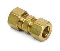
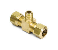
An inverted flare adapter is needed when connecting an inverted flare brake line to any component whose connection port uses a different fitting standard than inverted flare. Common situations requiring an inverted flare adapter include: connecting OEM steel brake lines to an aftermarket master cylinder or proportioning valve with AN-threaded ports (requires inverted flare to an fitting adapter); connecting OEM brake lines to a pressure sensor or gauge with NPT-threaded ports (requires inverted flare to NPT adapter); splicing two brake line sections using a union fitting (requires a double-ended inverted flare coupler, which is an adapter joining two inverted flare tubes); connecting to an imported vehicle component with metric brake line threads (requires an inverted flare to metric thread adapter); or adding a tee branch to an existing inverted flare brake line circuit (requires an inverted flare tee adapter). In each case, identify both connection types that the adapter must bridge, and verify both ends' specifications before purchasing.
An AN fitting (Army-Navy fitting, also called JIC or Joint Industry Council fitting) uses a 37-degree cone angle for its sealing surface, compared to the 45-degree angle of the inverted flare standard. AN fittings originated in military aircraft hydraulic systems in the 1940s and have become the standard in motorsport and high-performance automotive applications because they are available in reusable stainless steel and aluminum formats that mate with braided stainless steel or PTFE-lined hose assemblies. These braided hose assemblies have negligible thermal expansion (which can affect brake pedal feel in OEM rubber hoses under sustained heavy braking), are highly resistant to the abrasion and routing damage that affects rubber hoses, and are available in precise custom lengths for clean professional installations. Production vehicles use the inverted flare standard for their hard brake lines because it is manufactured at lower cost and performs reliably for the life of a normal road vehicle. AN fittings require an inverted flare to an fitting adapter to connect to OEM brake lines anywhere in the circuit where OEM and AN systems must be joined.
Inverted flare fitting bodies can generally be reused after disconnection if they show no damage to the seat surface, no corrosion or pitting at the seat, and no deformation of the thread. Inspect the fitting seat with good lighting after cleaning: any visible groove, scratch, or pitting in the cone surface indicates that the fitting body should be replaced because these imperfections create leak paths that cannot be eliminated by tightening the flare nut further. Flare nuts can be reused if the thread is undamaged and the flats are not rounded from previous wrench use, but flare nuts are inexpensive enough that replacing them during brake line service is generally recommended to ensure the full clamping capacity specified in the torque table. The inverted flare formed on the tube itself is deformed into the fitting seat during the initial tightening and cannot be reliably re-seated in a different fitting body after disconnection: if a tube is disconnected, the tube end should be inspected and if any damage or deformation is visible, the tube end should be cut off and a new inverted flare formed before reconnecting.
Working on inverted flare brake line fittings requires a specific set of tools that differ from general plumbing or hydraulic fitting work. The essential tools are: a dedicated double-flare or inverted-flare brake line flaring tool (not a standard SAE single-flare tool) with the correct size inserts for the tube OD being worked on; a tube cutter sized for brake line tubing (typically 3/16 inch to 1/4 inch capacity) that produces a clean square cut without distorting the tube; a tube deburring tool or the integrated reamer on the tube cutter; a set of brake line wrenches (line wrenches or flare nut wrenches) in the sizes corresponding to the inverted flare fitting flats (typically 10 mm, 11 mm, and 14 mm for metric vehicles, or 3/8 inch, 7/16 inch, and 1/2 inch for US-spec vehicles); a calibrated torque wrench covering the 10 to 20 ft-lb range for final tightening; and optionally a thread pitch gauge for identifying unknown fitting thread sizes. For inverted flare to an fitting adapter work, AN fitting wrenches in the appropriate dash sizes are also needed for the AN end of the connection.
Add:Xingzhong Road DianKou Town Zhuji City Zhejiang Province China
Mob: 0086-139 8951 3573
Tel: 0086-575-87560582
Fax: 0086-575-87560582
E-mail:[email protected]

 英语
英语 西班牙语
西班牙语