24Hours Tel
0086-139 8951 3573
Free Inqiry
E-mail:[email protected]
24Hours Tel
0086-139 8951 3573
Free Inqiry
E-mail:[email protected]
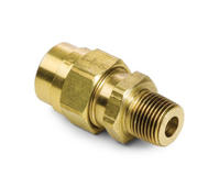
Compression fittings are mechanical connectors that join two tubes or pipes, or connect a tube to a component such as a valve or instrument, by using compressive force to create a leak tight seal rather than relying on threads, welding, or adhesive bonding. They are among the most widely used pipe and tube connection methods in plumbing, hydraulics, instrumentation, refrigeration, and gas systems, valued for their ability to create reliable, pressure rated connections without specialized tools or heat application, and for the ease with which they can be disassembled and reinstalled when maintenance or system modification is required.
The direct answer for anyone evaluating compression fittings is this: a compression fitting works by tightening a nut over a deformable ring (called a ferrule or olive) that is compressed against the outer surface of the pipe or tube, creating a metal to metal seal that prevents fluid or gas leakage. The correct specification requires matching the fitting material and pressure rating to the fluid, pressure, and temperature of the application, and selecting between the two main design types (single ferrule and double ferrule) based on the vibration environment and sealing requirement. This article covers how compression fittings work, the types available, their applications, and how to install them correctly for reliable long term performance.
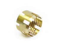
The sealing mechanism of a compression fitting relies on the plastic deformation of a ferrule (also called an olive or compression ring) as the fitting nut is tightened. The basic assembly consists of three components: the fitting body, the ferrule, and the compression nut. When the nut is tightened over the ferrule, it drives the ferrule into a tapered seat in the fitting body, compressing the ferrule radially inward against the outer surface of the pipe or tube. This compression creates a gas tight and liquid tight seal at two interfaces simultaneously: between the ferrule and the pipe outer surface, and between the ferrule and the fitting body seat.
The quality and reliability of a compression fitting seal depends critically on the deformation behavior of the ferrule material relative to the pipe material. Ferrules that are too hard will not deform adequately and will not seal; ferrules that are too soft will deform excessively and may extrude rather than creating a controlled seal. Quality compression fittings from reputable manufacturers specify ferrule hardness within a defined range of the pipe material hardness to ensure optimal deformation behavior during assembly.
Two principal compression fitting designs are used across different application sectors, and the choice between them has significant consequences for sealing performance, vibration resistance, and the range of tubing materials that can be used:
Compression fittings are produced in a wide range of configurations, materials, and pressure ratings to suit the diverse requirements of the industries in which they are used. Understanding the main types and their appropriate applications is the starting point for correct fitting selection.
The material of the fitting body and ferrule must be compatible with the fluid being conveyed, the system pressure and temperature, and the environment in which the fitting is installed. The main material options and their typical applications are:
| Material | Typical Applications | Key Advantage | Limitation |
|---|---|---|---|
| Brass | Plumbing, gas, water, HVAC, refrigeration | Low cost, easy machining, good corrosion resistance in water | Susceptible to dezincification in aggressive water; not for ammonia service |
| Stainless steel 316 | Instrumentation, high pressure, chemical, food processing | Excellent corrosion resistance, high temperature and pressure capability | Higher cost; susceptible to chloride stress corrosion cracking in some conditions |
| Stainless steel 304 | General industrial, non marine environments | Good corrosion resistance at lower cost than 316 | Less resistant to chlorides than 316; not for marine use |
| Copper | Domestic plumbing, refrigeration | Excellent for potable water; antimicrobial properties | Not suitable for ammonia or certain acids; soft material limits pressure |
| Nylon and polymer | Pneumatics, irrigation, low pressure fluid systems | Lightweight, corrosion immune, low cost for low pressure use | Limited temperature and pressure range; UV degradation risk outdoors |
Compression fitting leaks in service are almost always caused by installation errors rather than by fitting defects, and most installation errors are preventable by following the correct procedure for the specific fitting design being used. The following procedure applies to standard single and double ferrule compression fittings in metal tubing applications.
One of the practical advantages of compression fittings over welded or brazed connections is their ability to be disassembled for maintenance and reassembled reliably. For double ferrule fittings, the reassembly procedure after the first make up is different from the initial make up: the nut should be tightened to the snug position and then advanced only a small additional amount (typically one quarter turn or less) to achieve a seal, because the ferrule has already been permanently deformed to fit the tube and fitting body geometry from the initial make up. Overtightening a previously made up connection advances the ferrule further than necessary, reducing its remaining deformation capacity for subsequent reassemblies. Quality double ferrule compression fittings from reputable manufacturers are rated for multiple reassembly cycles without loss of sealing integrity when the correct reassembly torque is applied, making them genuinely reusable components rather than single use consumables.
Compression fittings used in regulated applications including gas distribution, pressure vessels, and process industries must comply with applicable national and international standards that specify dimensional, material, and performance requirements. The main standards governing compression fittings in different market sectors are:
Pressure ratings for compression fittings vary enormously with fitting size, material, and design. As a general guide, brass compression fittings in standard plumbing sizes are rated for 15 to 25 bar working pressure in water service at ambient temperature. Stainless steel double ferrule instrumentation fittings in small tube sizes (6 mm to 12 mm outer diameter) are commonly rated for 200 to 700 bar at ambient temperature, with ratings reducing at elevated temperatures according to the material's pressure temperature de rating curve. Always verify the pressure and temperature rating of any compression fitting against the maximum working pressure and maximum operating temperature of the specific system before installation, including any pressure surges or thermal excursions that the system may experience during normal operation or fault conditions.
Add:Xingzhong Road DianKou Town Zhuji City Zhejiang Province China
Mob: 0086-139 8951 3573
Tel: 0086-575-87560582
Fax: 0086-575-87560582
E-mail:[email protected]

 英语
英语 西班牙语
西班牙语